
How floating board-to-board connectors got off the ground.
By Daniel West, Lead Technical Applications Engineer at KYOCERA AVX.
Connecting things is intuitive. We all start doing this from a young age, and electronic connector standards like RJ45, USB-C, M.2 etc. may lead some design engineers into thinking interconnect solutions are intuitive as well, but they can get pretty complex.
The board-to-board (BTB) connector solution is straightforward, the issue of connecting two PCBs in parallel or at a right angle is easy to imagine even if it hasn’t been run into. The “floating” BTB connector needs more explanation, and—even then—this doesn’t necessarily explain why we’d need them. But they are used widely in handhelds, wearables, VR/AR headsets, and automotive electronics, to name just a few, so it is worthwhile to understand why this feature may be required.
Floating BTB connectors have the benefit of absorbing some of the mechanical stress when connecting the plug and receptacle. This is achieved by converting the plug or receptacle into a two-piece element that is held in place by the contacts. The contacts essentially act as a stiff spring between the two pieces of molded plastic that make up the body of the plug or receptacle, allowing the connected PCB assembly to wiggle, thereby making it seem as if the board was floating. This is predominantly intended to absorb forces in the X and Y directions during and after connection.
If there is a blind connection process, or if the connection process is automated, forcing the connection can be catastrophic to the connector if there is a misalignment. Fine pitch (0.5mm typical) connector applications for high density signal pins in size-constrained designs would be more prone to these issues, but they can also affect larger connectors. Many of these connectors are surface-mount technology (SMT) and shift slightly during reflow. This seems negligible at first, but if the plug and receptacle shift in the opposite direction, even a fraction of a millimeter can prevent a solid connection.
Speaking of reflow, this can sometimes lead to flux or other particles adhering to the contact surface of the pins, and reliable contacts have a wiping system that removes particles before the electrical contact surfaces touch. BTB connectors, typically the smaller ones with a low profile, can be used to terminate FPCs. Although there are FPC connectors, BTBs work better for designs that need to be slim, or have odd housing for the circuit, and only a force normal to the mounting surface can be applied to connect boards. These can require blind manual connection processes and the floating feature protects the connector while the contacts are getting compressed but not quite lined up.
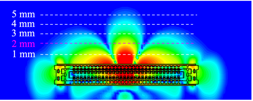
The push for smaller electronics and unique geometries drove the advancement of floating BTB connectors and hopefully sheds some light on why they are called floating. One of the more recent advancements for BTB connectors is high frequency performance. Data rates are so high that the shape of the contacts can impede or radiate signals leading to EMI issues. These can be shielded though, and contact shapes are designed for optimal performance. Floating and high-frequency-capable BTB connectors from Kyocera-AVX are just a few examples of how interconnect advancements enable the modern electronics we see every day.