
Enhancing stability and protection in power op-amps
Chandler Porter, Marketing Communications at Apex Microtechnology.
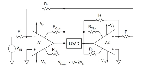
As shown in the illustration, the most common variation of a bridge connection using power op-amps occurs where one amplifier (A1) is the leader, and the second amplifier (A2) is the follower. The leader amplifier accepts the input signal and provides the gain necessary to develop full output swing from the input signal. The total gain across the load will be twice the gain of the leader amplifier.
The leader amplifier can be set up in virtually any op-amp circuit: inverting or non-inverting, differential, or as a current source such as an improved Howland Current Pump. You should always configure the follower as a unity gain inverting amplifier and drive it from the output of the leader.
Proper protection is essential for a leader-follower configuration in power op-amps. The illustration exemplifies this, showcasing op-amps with external current limiting. To optimize protection, set the leader’s current limit 20% lower than the follower’s. If adjusting the leader isn’t feasible, then raise the follower by 20% above the leader.
In case of a fault like a load short, the leader’s current limit triggers, causing output clipping. As the leader drives the follower, we are effectively clipping both, evenly sharing safe operating area (SOA) voltage stress. However, with fixed internal current limits in op-amps, ensuring the leader limits first is impossible. Thus, in fault conditions, it’s uncertain if SOA voltage stress is shared, potentially burdening one amplifier entirely.
Stability considerations for the follower
Ensuring stability for the follower amplifier, which functions as a unity gain inverter, is crucial. Stability enhancement methods invariably involve a tradeoff of frequency response. Fortunately, in the case of the bridge, the leader amplifier bandwidth is naturally restricted by operating at higher gains (as well as easing stability considerations for the leader).
Usually, the follower can be compensated to match both halves’ bandwidths, favoring noise gain compensation. Keep in mind that noise gain compensation depends on the non-inverting input being connected to a low impedance (<0.1RN). This is not a problem when the non-inverting input can be grounded, as in split supply applications, but it must be considered in single supply applications as the half supply voltage reference point must be a good AC ground. The simplest way to ensure a good AC ground is determined by good bypassing in the form of a tantalum or electrolytic capacitor in parallel with a ceramic capacitor.
Stability considerations for the leader
In the case of the leader, as well as the follower, capacitive loads should be considered. The leader may require noise gain compensation for very low gains, capacitive loading, or amplifiers with minimal phase margin. Amplifiers with emitter or source follower outputs usually handle inductive loads well. However, collector or drain output amplifiers with local feedback loop in the output stage, or monolithic amplifiers with quasi-complementary output stages, may oscillate into inductive loads. Compensate these amplifiers with a series R-C “snubber” from each amplifier output to ground.
Apex Microtechnology offers a range of dual-channel devices that offer a bridge configuration within a space-saving package. Alongside our product lineup, Apex offers valuable resources, including application notes that cover a variety of analog design challenges.